- How to Optimize SPWM on ATmega328P from 10kHz up to 24kHz.
- Understanding SPWM on ATmega328P
- Measuring ISR Execution Time
- Main Bottleneck: Floating Point Operations
- Arithmetic optimization
- Replacing digitalWrite with Direct Port Manipulation (DMP)
- Remove delayMicroseconds() inside ISR.
- Can We Go Beyond 24kHz?
- Final Conclusion
- Advanced Performance Tips
How to Optimize SPWM on ATmega328P from 10kHz up to 24kHz.
Increasing SPWM frequency from 10kHz to 24kHz on an ATmega328P SPWM driver card is not as simple as changing a timer value. Without proper optimization, the system becomes unstable, PWM glitches appear, and in worst cases, MOSFETs may fail.
In this comprehensive guide, we will deeply discuss:
- Basic SPWM concept on ATmega328P
- Timing calculation for 10kHz vs 24kHz
- ISR execution time analysis
- Why floating point slows down the system
- Direct port manipulation
- Deadtime and shoot-through risk
- Using NOP for switching control
- CPU timing margin calculation
This article is intended for inverter builders, SMPS developers, and power electronics enthusiasts using Arduino Nano or ATmega328P.
Understanding SPWM on ATmega328P
SPWM (Sinusoidal Pulse Width Modulation) generates a sinusoidal waveform by modulating a high-frequency PWM carrier.
The principle:
- Create a sine lookup table. Using a look up table to update the duty cycle provides the fastest execution time compared to directly calculating the sine value for each duty cycle update time.
- Duty cycle updates are performed on an interrupt service routine (timer ISR) periodically.
- Use timer interrupt for precise timing.
Timer ISR operations must finish before the next timer interrupt arrives, timing discipline is critical.
Measuring ISR Execution Time
To ensure that the ISR operation is completed before the next timer interrupt occurs, we must measure the execution time of the ISR operation.
To know the ISR duration accurately, we can use the debug pin.
Example:
ISR(TIMER1_OVF_vect) {

  PORTB |= (1 << 0);    // Debug start
  // SPWM process here
  PORTB &= ~(1 << 0);  // Debug end
}
pulses will be output at pin 17 (FanCtr) on the SPWM board, then measure the pulse width using an oscilloscope.
Pulse width = ISR execution time.
Measurement at 10 kHz
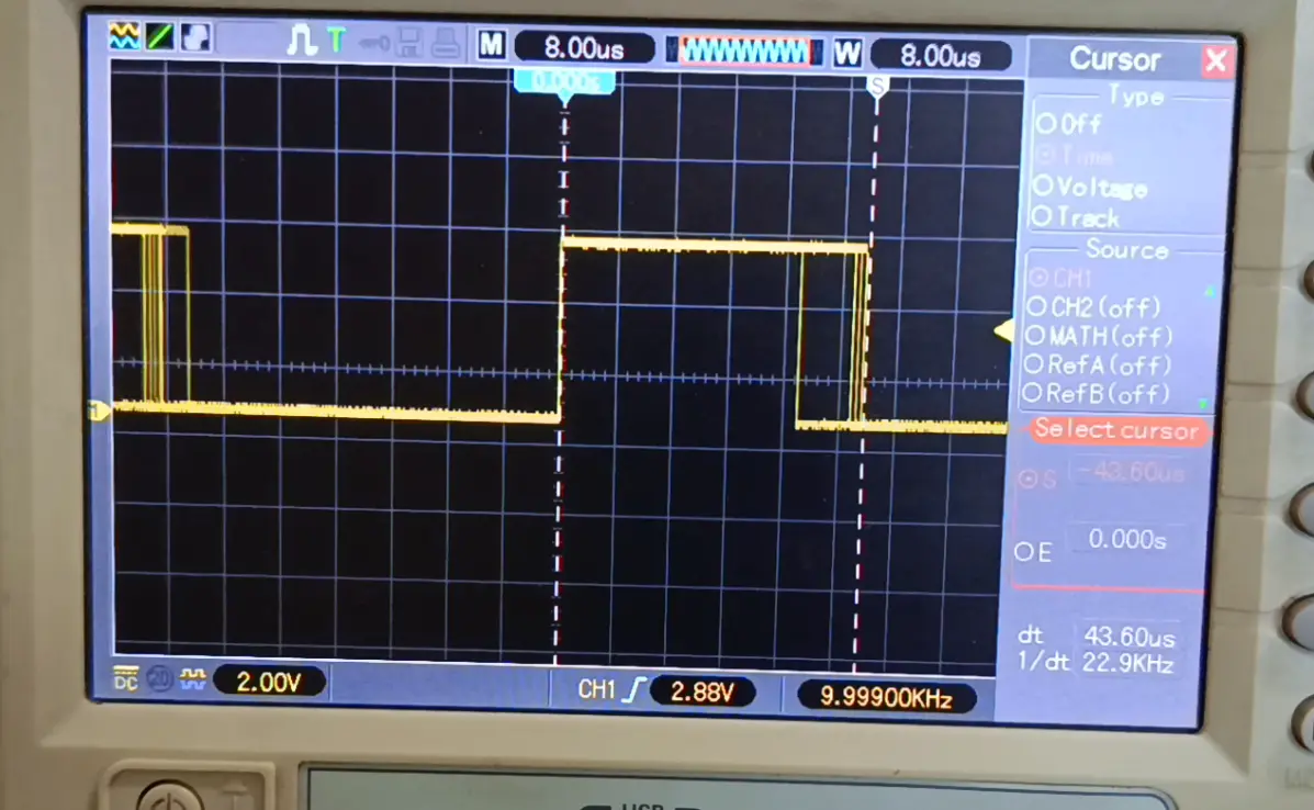
Oscilloscope captures for the unoptimized code show an ISR execution time of around 44 uS, we can see that the duty cycle is still below 50%.
period = 1 / 10000 = 100 uS
So that leaves about 56 uS of time, which is enough to carry out other tasks such as feedback processing.
Measurement at 24 kHz
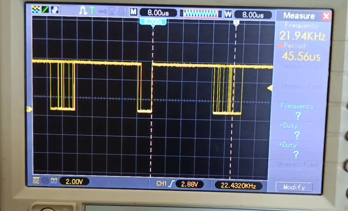
At 24 kHz the period value becomes 41.67 uS which is less than the ISR execution time, as a result:
- Next interrupt arrives before completion
- Interrupt nesting occurs
- PWM output becomes unstable
This is the root cause of failure at 24kHz.
Main Bottleneck: Floating Point Operations
In the ISR code there are floating point calculations that are performed twice:
  OCR1A = int(LUT[num] * percentMod) + dtA;
  OCR1B = int(LUT[num] * percentMod) + dtB;
The issue:
- ATmega328P has no FPU
- All floating point is emulated in software
- Each float multiplication costs hundreds of cycles
This is the main reason ISR consumed 44 µs.
Arithmetic optimization
To speed up execution time, I need to minimize floating-point calculations. Here, there are two floating-point calculations, which I’ll shorten to just one.
So the code snippet above becomes:
  int OCR_val = int(LUT[num] * percentMod);
  OCR1A = OCR_val + dtA;
  OCR1B = OCR_val + dtB;
By eliminating one floating point calculation the ISR execution time is reduced significantly. I got a time saving of about 20 uS.
Replacing digitalWrite with Direct Port Manipulation (DMP)
To control the 50 Hz fundamental signal previously I used code like the following:
digitalWrite(fund1, LOW);
digitalWrite(fund2, HIGH);
Using the standard Arduino library commands has a fairly long execution time due to the overhead of the library that is also executed.
Then I use the Direct Port Manipulation method to speed up the execution time:
 PORTB &= 0b11110111;      // fund2 Off
 PORTD |= 0b00001000;      // fund1 On
Performance comparison:
- digitalWrite ≈ 3–5 µs
- Direct port ≈ tens of nanoseconds
In a high-speed ISR, this difference is massive.
DMP consequences : Shoot-Through Risk
Since direct port switching is very fast, the default dead time may be too fast (in the order of tens of nanoseconds), I’m worried that a shoot-through will occur as a result.
If two MOSFETs turn on simultaneously (shoot-through condition) :
- Direct short circuit occurs
- Extremely high current spike
- MOSFET damage is likely
Deadtime must be controlled deliberately.
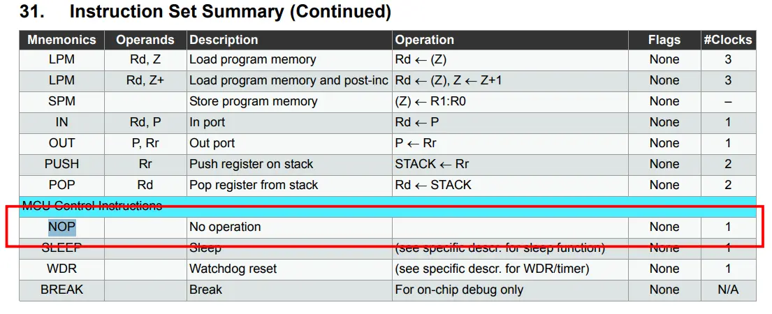
Adding Deadtime Using NOP Instructions
I added a command to the assembly called “nop,” or “no operation”. This command does nothing but waste a machine cycle (1 clocks).
So the code becomes like this:
 PORTB &= 0b11110111;      // fund2 Off
 asm volatile("nop");
 asm volatile("nop");
 PORTD |= 0b00001000;      // fund1 On
Each NOP = 1 clock cycle.
At 16 MHz:
- 1 clock ≈ 62.5 ns
- 2 NOP ≈ 125 ns
Deadtime can be tuned by adjusting NOP count.
Remove delayMicroseconds() inside ISR.
Bad practice:
delayMicroseconds(60);I use the delayMicroseconds() command to set the fundamental signal change time, but using this function inside an ISR is not a good practice. This command will block the ISR for a certain time.
An ISR must execute as fast as possible.
To get rid of this, I rearranged the logic structure inside the ISR as follows:
ISR(TIMER1_OVF_vect) {
  static int ph;
  static int dtA; //= 0;
  static int dtB; //= 5;

 // PORTB |= (1 << 0);  // debug pin (rising)
  if (num== 0) {
    if (ph == 0) {          // OC1A as SPWM out
      TCCR1A = 0b10110000;  // clear OC1A, set OC1B on compare match
      dtA = 0;              // no dead time
      dtB = 5;              // adding dead time to OC1B
    } else {
      TCCR1A = 0b11100000;  // OC1B as SPWM out
      dtA = 5;
      dtB = 0;
    }
    PORTB &= 0b11110111;    // 1HO & 1LO Off
    PORTD &= 0b11110111;
    ph ^= 1;
  }
  if (num== 1) {
    if (ph == 1) {
      PORTB &= 0b11110111;      // fund2 Off
      asm volatile ("nop");
      asm volatile ("nop");
      PORTD |= 0b00001000;      // fund1 On
      phs = 1;
    } else {
      PORTD &= 0b11110111;      // fund1 Off
      asm volatile ("nop");
      asm volatile ("nop");
      PORTB |= 0b00001000;      // fund2 On
      phs = 0;
    }
  }
  num++;
  int OCR_val = int(LUT[num] * percentMod);   // OCR1x value for next update
  OCR1A = OCR_val + dtA;
  OCR1B = OCR_val + dtB;
  if (num>= samples) num=0;
//  PORTB &= ~(1 << 0); // debug pin (falling)
}
After removing the delay, ISR improved significantly.
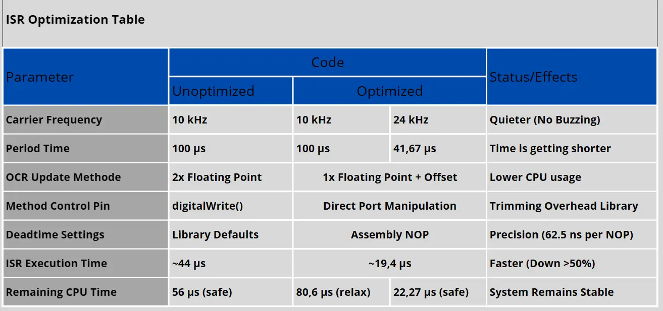
Final Optimization Results
After all optimization:
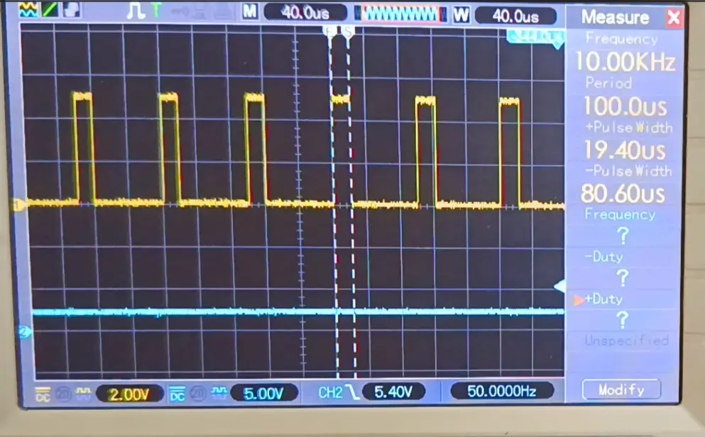
ISR reduced from 44 µs → 19.4 µs.
At frequency 10kHz (period = 100 µs) :
Remaining CPU margin ≈ 80.6 µs, there is still plenty of room to run other functions outside of interrupts
This means:
At frequency 24kHz (period = 41.67 µs) :
Remaining CPU margin ≈ 22.7 µs, there is still enough space to run other functions outside of interrupts.
Can We Go Beyond 24kHz?
Theoretically:
If ISR = 19 µs
Maximum frequency ≈ 52 kHz
But practically:
- Safety margin is required
- Feedback loop requires CPU time
- Switching losses increase
24kHz is often an optimal balance between switching performance and CPU load.
Final Conclusion
The real issues were:
- Excessive floating point usage
- digitalWrite overhead
- Delay inside ISR
- Inefficient ISR structure
With proper optimization:
- ISR reduced from 44 µs to 19.4 µs
- SPWM 24kHz runs reliably
- ATmega328P remains highly relevant for inverter projects
Advanced Performance Tips
To push performance further:
- Use 256 or 512-point sine table
- Precompute scaling values
- Avoid division inside ISR
- Avoid function calls inside ISR
- Access hardware registers directly
- Keep ISR as short and deterministic as possible