▶️ Watch on YouTube …
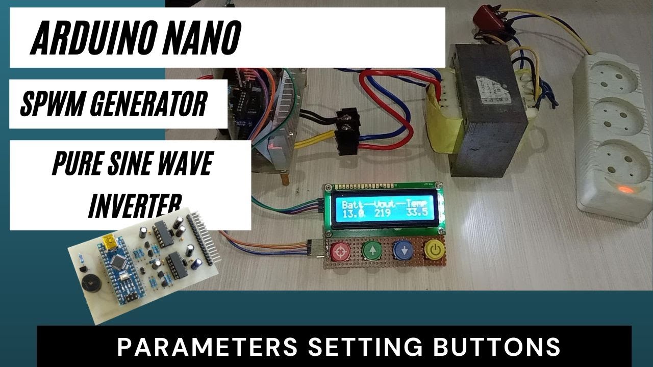
Intro
Sometimes we need to change the Inverter parameters, and we do that by changing the values by editing the code.
By adding buttons we can make parameter changes easily, there is no need to change coding and upload to Arduino.
Just add four buttons and use the internal EEPROM on the ATmega328 we can change and save parameter values.
Adding Buttons
Below is the buttons switch to add:
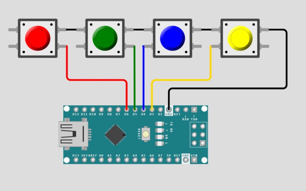
Connect the push-on switch to pins D3, D4, D5 and D6 on the Arduino Nano. The other leg of the switch is all connected to the ground.
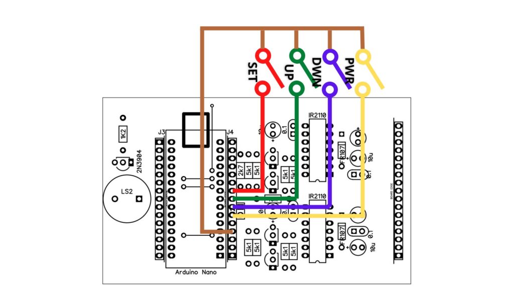
On the PCB I provided a header for that added feature, so just connect the switch to the header.
For circuits and PCBs please see the post about the Arduino Nano SPWM generator.
Adding Code
Started by creating a small SPWM Arduino program, and it turned out to be quite fun to develop further.
Variable Naming
As the program grows, it makes it harder to read. So I made improvements first, namely by naming a value so that it becomes more meaningful and easier to understand.
For example, one part of the program contains:
  alrm = constrain(vfbIn, 462, 660);
  if (alrm != vfbIn) alrmCnt++;
  else
    alrmCnt = 0;
  if (alrm == 462 && alrmCnt >= 150) alarmIndication(2);
  if (alrm == 660 && alrmCnt >= 15) alarmIndication(3);
You see two values, 462 and 660, which are values for underVoltage and overVoltage, and they appear twice each. Changing the value 462 to the underVoltage variable and 660 to the overVoltage variable will be easier to understand. In addition, the value 462 comes out twice, when we want to change both we have to change them. By naming it we simply replace one value so that it reduces errors when making changes.
So now the part becomes:
  alrm = constrain(vfbIn, underVoltage, overVoltage);
  if (alrm != vfbIn) alrmCnt++;
  else
    alrmCnt = 0;
  if (alrm == underVoltage && alrmCnt >= 150) alarmIndication(2);
  if (alrm == overVoltage && alrmCnt >= 15) alarmIndication(3);
Then define it as a variable at the beginning of the program. As follows:
volatile int fanOnTemp=800,
          fanOffTemp =679,
          fanOverTemp=924,
          underVoltage = 462,
          outputVoltage = 612,
          overVoltage = 645,
          lowBatt = 470,
Pay attention to the code above, the overVoltage value is 645 which previously was 660. By changing this value all overVoltage values that were originally 660 are now 645.
In addition, I also named the Arduino pin with the appropriate name as follows:
const byte vfbPin = A0,
           tfbPin = A1,
           battPin = A2,
           JP = 2,
           buttonOnOffPin = 3,  //PD3
           buttonDownPin = 4,   //PD4
           buttonUpPin = 5,     //PD5
           buttonSetPin = 6,    //PD6
           buttonPin = 120,     //0b0xxxx000 --> button pin mapped to port D
           buzzerCtl = 7,       //PD7
so that
pinMode(ledBuiltIn, OUTPUT);easier to understand than:
pinMode(13, OUTPUT);I also define the addition of buttons by name, for example, buttonOnOffPin which is connected to the Arduino D3 pin.
Then I started writing code for reading buttons and storing parameters in the EEPROM.
Code for Button and EEPROM.
EEPROM
First, add the EEPROM library.
#include <EEPROM.h>Then in void setup(), I added port initialization for the button as input with internal pull-up thus simplifying the circuit
  pinMode(buttonUpPin, INPUT_PULLUP);
  pinMode(buttonOnOffPin, INPUT_PULLUP);
  pinMode(buttonDownPin, INPUT_PULLUP);
  pinMode(buttonSetPin, INPUT_PULLUP);
and codes to read the contents of the EEPROM
  EEPROM.begin();
  if (EEPROM.read(0) == 0) {
    lowBatt = (EEPROM.read(2)<<8) + (EEPROM.read(1));
    underVoltage = (EEPROM.read(4)<<8) + (EEPROM.read(3));
    overVoltage = (EEPROM.read(6)<<8) + (EEPROM.read(5));
    fanOverTemp = (EEPROM.read(8)<<8) + (EEPROM.read(7));
  }
On a new ATmega328, all EEPROM address locations will contain the value 255 (0b11111111 binary). So in this code, the first thing to do is to check the first address in the EEPROM. If it’s not zero, it means the EEPROM is new so there is no need to read its contents.
When the contents of this EEPROM.read(0) are zero, it indicates that the inverter parameters have been updated in SETUP mode.
Then the contents of the parameters stored in the EEPROM are read to replace the default parameters.
lowBatt = (EEPROM.read(2)<<8) + (EEPROM.read(1));The inverter parameter is an integer (16 bits wide) while the EEPROM is a byte (8 bits wide), so two EEPROM storage locations are needed for one inverter parameter. Even addresses for high bytes and odd addresses for low bytes, then both are combined back into one integer value. This is done by shifting left the even EEPROM value 8 times so that it becomes the high byte of the parameter, and then the odd EEPROM value is added as the low byte.
Reading the Buttons
Now let’s talk about coding for buttons.
Here I read the conditions of keystrokes by means of Port Manipulation, which is to read the port as a whole and process it. Usually, we use digitalRead which reads only one pin.
The reason why I use this method is simply that I want to try it that way, so it’s not for better or worse reasons.
Take a look at the Arduino Nano pinout as follows:
ATmega328 Port       PD0..PD7 PB0..PB5 etc.
Arduino Nano Pin      D0...D7  D8..D13 etc
It shows that D0…D7 on Arduino is PD0…PD7 on Atmega328, and D8…D13 is for PB0…PB5. Thus Port Manipulation for port D, namely PIND, will read pins D7…D0 (MSB first) while PINB will read D13..D8. From the picture of the switch circuit above, namely D3 for POWER, D4 for DOWN, D5 for UP and D6 for SET then:
ATmega328 Port       PD7  PD6  PD5  PD4  PD3  PD2  PD1  PD0
Arduino Nano Pin      D7   D6   D5   D4   D3   D2   D1   D0
                     buz  SET   UP  DWN  PWR   J2   RX   TX
*the port in italics is the i/o port already in use by the system
Because some of port D is already in use by the system, reading the port with the PIND command will return the button status value and other statuses.
In order to generate a value containing only the button state, it is necessary to remove the unnecessary port contents. Some of the D ports are already used by my programs such as TX, RX, J2 and buzzerCtl pins so these pins should be excluded from reading.
What I did was to use a bitwise AND pin D with the button location information (buttonPin) as follows:
PIND & 0b01111000
Logic 1 shows where the button is attached to the port, so the port D reading is:
PIND & buttonPin = 0b01111000 = no button pressed
                 = 0b00111000 = buttonPower pressed
                 = 0b01011000 = buttonDown pressed
                 = 0b01101000 = buttonUp pressed
                 = 0b01110000 = buttonSet pressed
                 = 0b01100000 = buttonSet and Up pressed simultaneously
That’s how the button reads, now let’s start with the big part.
Processing the Button
Because in the current code, the inverter is OFF and turned on by pressing the Power button, the first thing to do in the void loop() section is to check the Power status of the inverter.
  if(DDRB == 0) {
    if ((PIND & buttonPin) == buttonPower) {
      DDRB = 0b10011110;
      lcd.clear(); lcd.backlight(); lcd.setCursor(0, 0);
      lcd.print("Batt--Vout--Temp");
      while ((PIND & buttonPin) == buttonPower) delay(1);
    }
    return;
  }
When it reads DDRB = 0 (the inverter is off), the program will check for pressing the Power button.
Pay attention to the return; instructions which will make the program repeat the beginning, namely reading DDRB then reading the button and continuing like that until the button is pressed.
When the Power button is pressed, the output is turned on by changing the DDRB contents, then turning on the display and then the while instruction will hold the program here until the button is released.
After the button is released the program will execute a return; to the beginning i.e. checking DDRB, but currently, DDRB is not zero so the Power ON button check is now skipped.
Now in the Power ON condition. The program again checks the Power button but this time for the Power OFF function. When pressed the output will be turned off and then the program will repeat from the beginning as in the process of turning on the output.
  if ((PIND & buttonPin) == buttonPower) {
    DDRB = 0;
    lcd.clear(); lcd.noBacklight(); lcd.noCursor(); lcd.blink_off();
    while ((PIND & buttonPin) == buttonPower) delay(1);
  }
If Power OFF is not performed then check the SET and UP buttons to perform the parameter SETUP.
  if ((PIND & buttonPin) == buttonSetUp) {
    buttonTime = millis() - arduinoTime;
    if (buttonTime > 2000)  editParameters();
  } else arduinoTime=millis();
When not pressed the program will read and save the time from the Arduino since it was turned on, namely millis(); then complete all inverter routines as usual.
Function editParameters()
But when the SET and UP buttons are pressed, the length of time the button is pressed is calculated. By calculating the current time minus the last time before the button was pressed, we get the length of time the button was pressed. And if it’s been more than 2 seconds it will switch to the setup function which is editParameters():
void editParameters(){
  int lowBattTmp = lowBatt,
      underVoltageTmp = underVoltage,
      overVoltageTmp = overVoltage,
      fanOverTempTmp = fanOverTemp;
Here the operational variable will be copied to a temporary variable to be changed without disturbing the operational variable
Then display the parameters and their values which we will change later.
Because the content of the variable is a 10-bit value, the value is displayed on the LCD after being converted to the value we normally read.
  lcd.clear();
  lcd.print("  Low Battery: ");
  lcd.setCursor(6, 1);
  lcd.print(float(lowBatt/512.0*systemBatt),1);
After that, the program again checks the keystrokes.
The process carried out is the same as the process on Power On or OFF, but the variable that is now being changed is the inverter parameter variable.
So the detailed process of changing the inverter parameter variable will not be discussed again here.
Lastly is about SAVE or CANCEL.
When CANCEL is selected, execution exits editParameters() without changing anything and returns to the execution of the instructions in the loop.
Saving Parameters
But when SAVE is selected, the value of the temporary variable will be copied to the running variable, thus the inverter is currently using the new parameters. In addition, the parameter values are stored in the EEPROM for use in the next inverter operation.
  if ((PIND & buttonPin) == buttonSet) {
    lowBatt = lowBattTmp;
    underVoltage = underVoltageTmp;
    overVoltage = overVoltageTmp;
    fanOverTemp = fanOverTempTmp;
    EEPROM.update(0, 0);
    EEPROM.update(1, lowByte(lowBatt));
    EEPROM.update(2, highByte(lowBatt));
    EEPROM.update(3, lowByte(underVoltage));
    EEPROM.update(4, highByte(underVoltage));
    EEPROM.update(5, lowByte(overVoltage));
    EEPROM.update(6, highByte(overVoltage));
    EEPROM.update(7, lowByte(fanOverTemp));
    EEPROM.update(8, highByte(fanOverTemp));
    lcd.clear();
    lcd.println("    UPDATED       ");              // update done
    delay(1000);
  }
EEPROM address 0 is filled with a zero value as a flag that the EEPROM already contains an update value.
Then the next address is filled with parameters to be stored, each parameter occupies an EEPROM address. This is because the parameter has an integer type (2 bytes or 16 bits) while the EEPROM storage is bytes (8 bits), so I save the parameters into two, namely the high byte and low byte sections.
After everything is saved, the next execution is to exit the editParameters() function and resume execution in the void loop().
That’s an explanation of coding to change inverter parameters via buttons stored in EEPROM, please also see the video that accompanies this article.
Hopefully, this is useful for all of us, see you next time……
Please I want complete circuit diagram
Circuit diagram please refer to https://yopiemaker.com/lcd-16×2-for-arduino-nano-spwm-generator/
then you need to connect the push button to this circuit
Hola amigo gracias por compartir su conocimiento que es de gran ayuda boy a agregar estos códigos.
Cómo haría para ingresar también a una pantalla lcd 20×4 un medidor de potencia en watts usando un un un medidor de corriente ejemplo como el acs712 ,. O un mini transformador de corriente o recistecias shunt con un operacional me interesa mucho todo sobre inversores es mi pasión espero una respuesta gracias amigo.
Hola, sigo probando con el sensor de corriente y sigo sin obtener buenos resultados. Lo compartiré si obtengo buenos resultados.
При подключении к аккумулятору сразу выскакивает ошибка “короткое замыкание”подскажите что может быть ?
Индикация короткого замыкания при простом включении происходит из-за того, что обратная связь по напряжению не обнаружена. проверьте раздел vfb, здесь должно быть пиковое напряжение 3 В.
какой транс?
Я не понимаю вопроса, пожалуйста, объясните подробнее
Трансформатор на 6в или 12в на вторичной обмотке?
Я использую старый трансформатор ИБП на 7 В, но трансформатора на 6 В будет достаточно.
Я все понял спасибо.