▶️ Watch on YouTube …
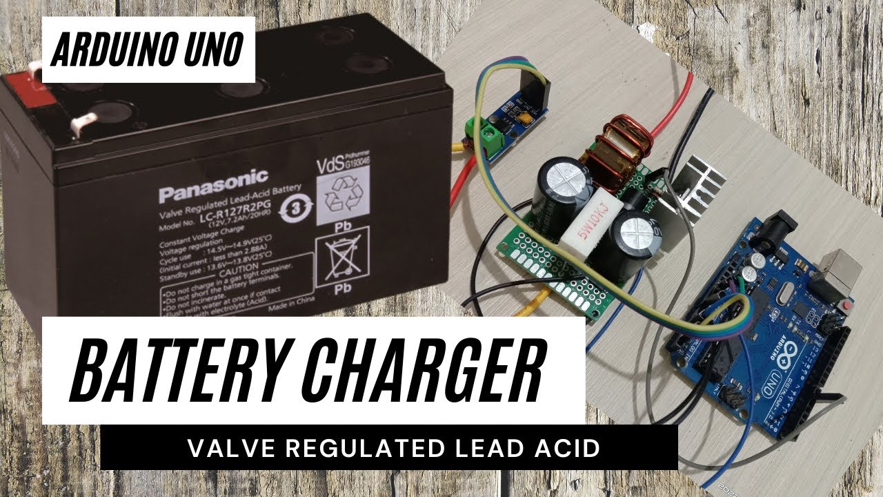
This post is about designing a battery charger using Arduino Uno as a continuation of the DC boost converter project. I made some small additions to hardware and software which I will discuss here. I have a 12V/7.2AH VRLA battery so my project aims to make a charger for it.
Battery Charging Method
To do this I apply the charging method in the Charging Lead Acid article on batteryuniversity.com. For more details, please visit the link I shared. I will only describe the points which I will then try to translate into the Arduino program.
The first thing I note is that the lead acid battery uses the Constant Current Constant Voltage method or CCCV. Charging is carried out in three stages, which are [1] constant-current charge, [2] topping charge and [3] float charge.
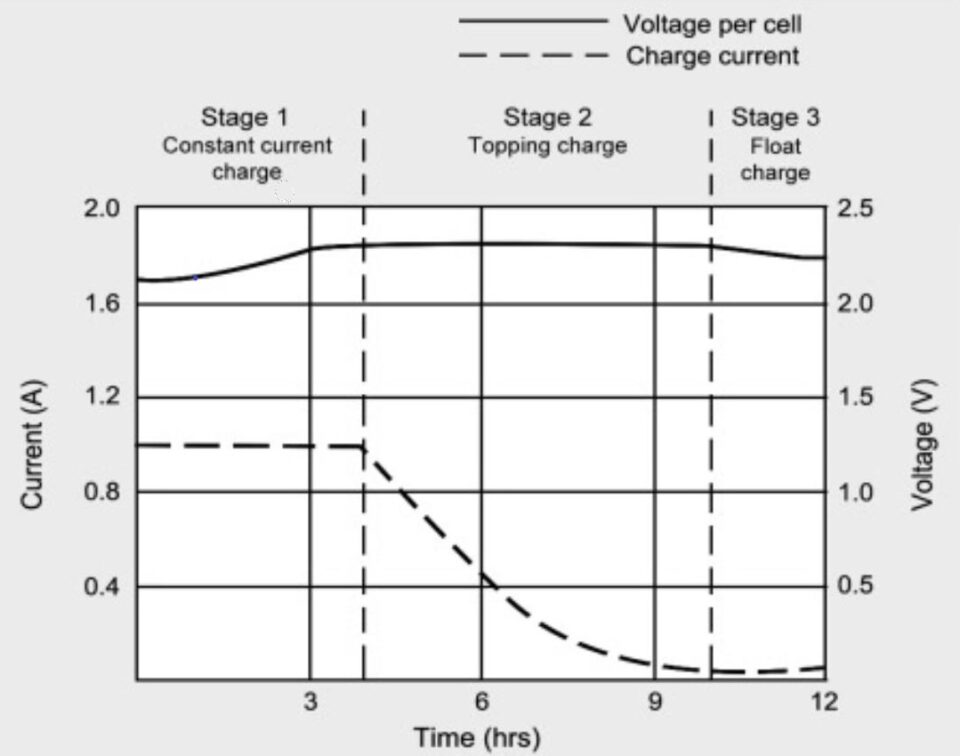
The picture above shows these three stages.
Stage [1]: The charger starts with Continuous Current mode. The current supplied to the battery is regulated so that it remains at a certain value, and the voltage without regulation it follows the battery voltage. At the end of this stage is the transition from CC to CV, both work alternately to adjust to the current conditions.
Stage [2]: Is Topping Charge which works in CV mode with the voltage set at a certain value. The topping charge continues at a lower charge current until it reaches saturation
Stage [3]: This is a Float Charger in CV mode at a lower voltage value to compensate for the self-discharge loss.
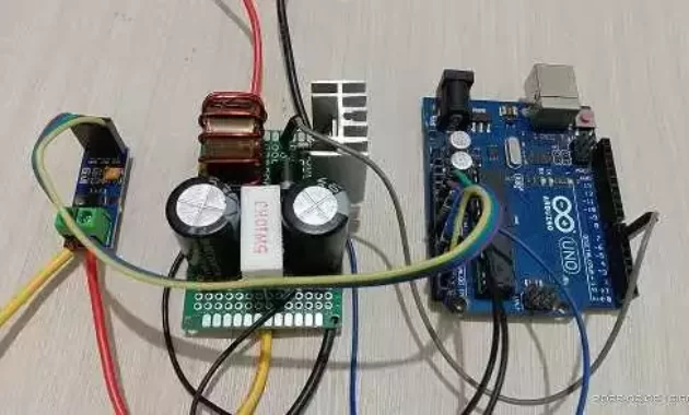
Battery Charger Circuit
The modification I made was to replace the reference voltage with a current sensor. I replaced the potentiometer with an ACS712/5A current sensor. The circuit itself is as follows:
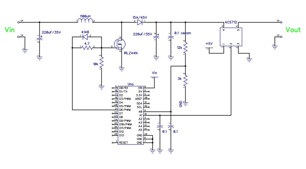
Please note in the photo above the 10k/5W resistor is a dummy load not shown in the schematic. The output voltage tends to be high if the output has not been loaded because the voltage is stored in the filter capacitor. It’s better to just install the resistor so that it functions as a minimum load because the regulation doesn’t work well without a load.
Charger Requirements
The VRLA battery I’m going to charge is something like this:
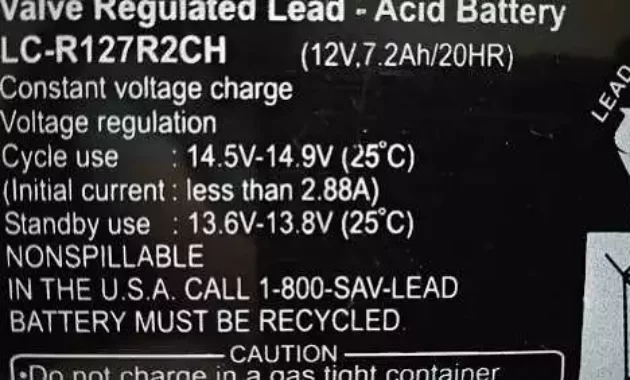
From here I specify the values for the parameters for the coding.
With a battery capacity of 7.2 Amperes, I will play it safe by only charging it at 10%, so I will set the charger at 0.7A. This value is far below the maximum Initial Current value of 2.88A.
The Cycle Use value shows 14.5V – 14.9V and I would use 14.7V or 2.45V/cell for that. According to the article, charging at this voltage is more consistent for capacity readings and also less sulfation.
Lastly is the Stand By voltage. According to the article above, the Float voltage is between 2.25V – 2.30V per cell, so I decided to use 13.7V. Meanwhile, I set the stand-by current at 0.1A.
Let’s Code
We already understand the meaning of the values above and now we have to convert these values into a form that the microcontroller understands.
Voltage readings (charge and float) are the result of a voltage divider circuit. The voltage across A0 is (3k / (3k+12k))Vout = 0.2 * Vout and is still an analogue voltage value. Then we convert it to a digital value of ((0.2 * Vout) / 5V) *1023 = 40.92 * Vout.
Thus the charging voltage (chgVoltage) is 14.7 * 40.92 = 601, and the stand-by voltage (stbyVoltage) is 13.7 * 40.912 = 560.
const int chgVoltage = 601;
const int stbyVoltage = 560;
ACS712 outputs 2.5V when no current is flowing, and when the current is flowing there is an offset voltage of 185mV/A. For example for 1A current, ACS712 voltage is 2.685V. So to make it a digital value is: ( 2.5 + Iin * 0.185) / 5) * 1023 = 511 + ( Iin * 37.8 ).
Thus the charging current (chgCurrent) is 511 + (0.7 * 37.8) = 537, and the standby current (stbyCurrent) is 511 + (0.1 * 37.8) = 515.
const int chgCurrent = 537;
const int stbyCurrent = 515;
For an explanation of coding void setup(), please see the DC Boost Converter post.
Charging Process
Next, I describe the process that occurs in the loop. It begins by reading voltage and current feedback and then processing this information to carry out the appropriate task.
 voltageFeedBack=analogRead(vfbIn);
 currentFeedBack=analogRead(ifbIn);
Without the battery installed there is no current flowing at the output, so currentFeedBack is less than chgCurrent. Thus the next instruction will increase or decrease the duty cycle (OCR0A++/OCR0A–) until it is at a standby voltage (float voltage) of 13.7V.
  if (currentFeedBack < stbyCurrent) {
    if(voltageFeedBack < stbyVoltage) OCR0A++;
    if(voltageFeedBack > stbyVoltage) OCR0A--;
  }
When we install an empty battery, the battery will try to draw a large enough current. Because previously the charger was set at stand-by voltage, when a load is attached, the voltage will drop due to insufficient power (due to low duty cycle). Then it will try to increase the power by increasing the duty cycle (OCR0A++) to the charging current.
  if (currentFeedBack > stbyCurrent && currentFeedBack < chgCurrent) {
    if(voltageFeedBack < chgVoltage) OCR0A++;
    if(voltageFeedBack > chgVoltage) OCR0A--;
  }
  if (currentFeedBack > chgCurrent) {
    OCR0A--;
  }
The voltage (Duty Cycle) will continue to increase until the currentFeedBack condition is equal to chgCurrent. And now we enter the charging mode stage [1].
Stage [1]
This is the current regulation stage of charging the battery.
The program part above will adjust the charging current to match the charging current. Currently, the charging mode is Continous-Current (CC), in this project, it will set the current at 0.7 amperes. The voltage itself will be below the charging voltage.
Over time, with a certain amount of charge going to the battery, the battery voltage will increase and the pulse width will decrease to compensate for the constant current.
  if (currentFeedBack > chgCurrent) {
    OCR0A--;
  }
After the feedback current is smaller than the charging current requirement, the stage[1] charging mode ends.
Stage [2]
The task at this stage is to stabilize the charging voltage at 14.7V. The current will gradually decrease until it reaches a standby current.
The control that occurs now is based on the state between voltageFeedBack and chgVoltage. If the indicated voltage increases, the pulse width decreases (OCR0A–) or vice versa (OCR0A++). Program execution still happens in parts like the code for step[1] but control is now based on voltage information.
This happens until the charging current value is below stbyCurrent of 0.1A which is the end of this stage.
Stage [3]
When the charging current is less than 0.1A, the charging mode switches to Float Charge. Here the voltage will change from charging voltage (14.7V) to standby voltage(13.7V).
  if (currentFeedBack < stbyCurrent) {
    if(voltageFeedBack < stbyVoltage) OCR0A++;
    if(voltageFeedBack > stbyVoltage) OCR0A--;
  }
The purpose of Float charge is to compensate for the self-discharge that occurs in all batteries.
After entering Float Charge mode, you can remove the battery or leave it plugged into the charger. Some people say it’s safe to leave it on but others say it’s best to take it off. Now it’s up to you.
Please click on the link below for the schematic and coding and also the video.
That’s all for now. May be useful…
Have a nice day
Why would you use a brutal crowbar as your regulator when you could have built a nice linear series regulator instead with the same parts count? Your crowbar risks destroying the power supply and itself and your expensive inductor.
“Thank you for your valuable feedback! This project is primarily an experimental study for me to explore PWM control using Arduino within a Boost Converter topology. At this stage, my main focus is on keeping the hardware and coding as simple as possible to ensure the basic concept works.
I acknowledge that aspects such as advanced safety, long-term reliability, and high efficiency were not the primary focus of this specific iteration. Your point regarding the risks of the crowbar circuit and the benefits of a linear series regulator is a great technical note, and I will definitely take it into consideration for future improvements. I appreciate you sharing your expertise!”