▶️ Watch on YouTube …
My post this time is about the DC-DC boost converter, which is a converter from 7V to 12V using Arduino. Here I try to design from start to finish.
The first step for this design was determining the proper specifications for my purposes.
What I need is the following:
Vin : 6V to 8V, Vout : 12V to 18 V, Imax : 5A
It seems that I want to increase the voltage so I choose the DC Boost Converter configuration for this purpose.
Boost Converter Design
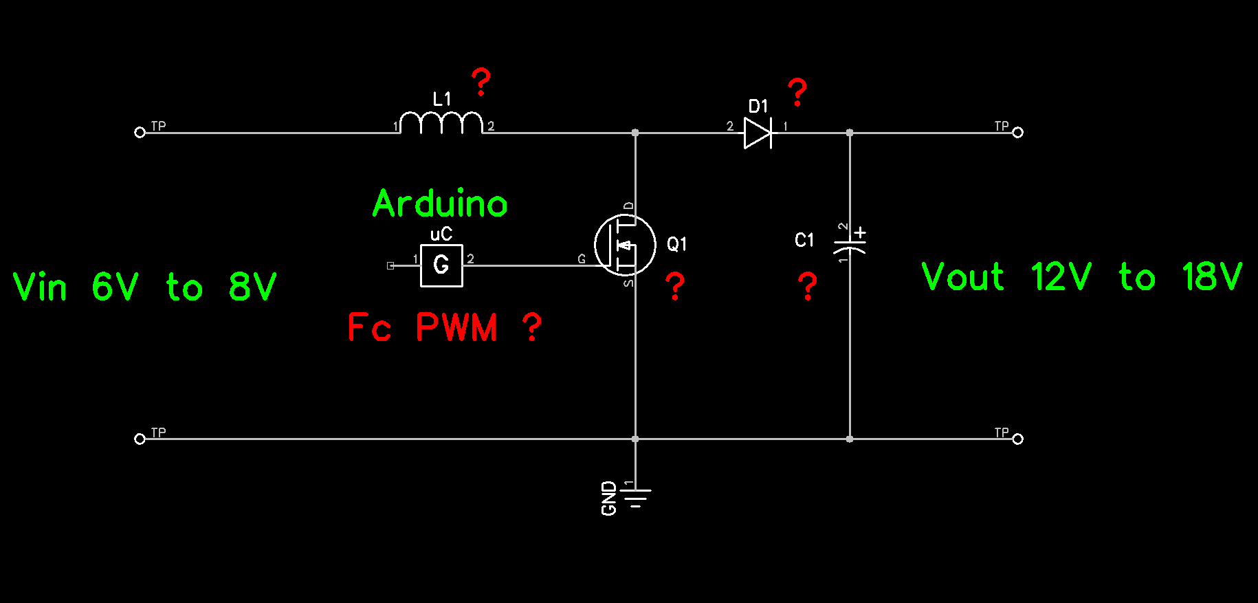
Next is to determine the component values i.e inductors, capacitors, diodes and MOSFETs to be used. Consider the basic circuit diagram of the converter below:
To calculate component requirements, I used the online boost converter calculator from Adafruit. You can visit here: https://learn.adafruit.com/diy-boost-calc/the-calculator
This is how the capture looks like
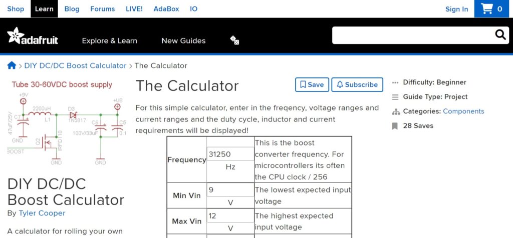
The first thing to enter in this calculator is the carrier frequency of the PWM.
I want to apply PWM at a fairly high frequency using timer0. The ATmega328 datasheet explains that the Fast PWM mode produces high frequencies. Besides that, the datasheet also explains this:
This high frequency makes the fast PWM mode well suited for power regulation, rectification, and DAC applications. High frequency allows physically small sized external components (coils, capacitors), and therefore reduces total system cost.
ATmega328P datasheet, page 80
The clock frequency on the Arduino Board is 16MHz so the PWM frequency that I get is 62.5kHz. Thus I input the value of the frequency and input-output voltage into the calculator. For ripple, I don’t need a small value yet so I try with 0.5V.
And here are the results:
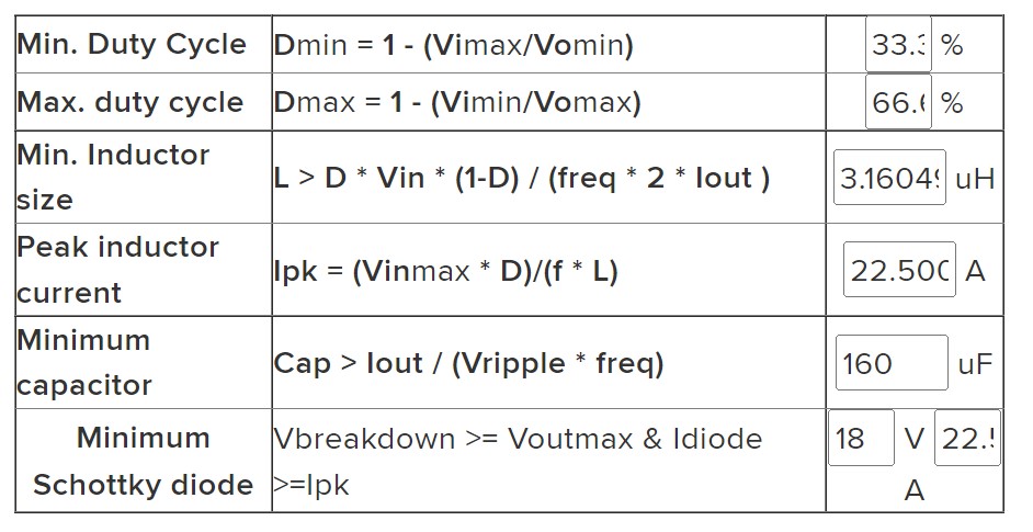
What I get is a limit of minimum/maximum duty cycle values, and minimum values of capacitors, inductors and diodes required.
For the switch, I use the IRLZ44N Logic MOSFET which works at the TTL level, in contrast to the IRFZ44N which requires a driver circuit to work at TTL.
Lastly, I added a voltage divider circuit from the output to pin A0 as voltage feedback, and a potentiometer trimer for the reference voltage connected to pin A1.
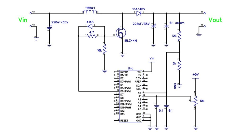
Please note in the photo above the 10k/5W resistor is a dummy load not shown in the schematic. The output voltage tends to be high if the output has not been loaded because the voltage is stored in the filter capacitor. It’s better to just install the resistor so that it functions as a minimum load because the regulation doesn’t work well without a load.
The Code for Boost Converter
In the design of this Boost Converter, I include voltage feedback and an output voltage that can be changed. So I need two analogue inputs as feedback and reference, besides one PWM output to control the MOSFET.
int vfbIn=A1;       // feedbackVoltage connected to A1
int potIn=A0;       // voltage addjust potentiometer to A0
int pwmOut=6;
The code above is for defining I/O ports on Arduino. Voltage feedback vfbIn is connected to pin A1, voltage regulation potIn to pin A0 and output pwmOut to pin D6.
void setup();
void setup() {
  TCCR0A = 0b10000011;    // Fast PWM (mode 3), Clear OC0A on compare match
  TCCR0B = 0b00000001;    // no prescaler fc = 16MHz/256 = 62.5kHz
  OCR0A=84;               // init  33% duty cycle
  pinMode(pwmOut,OUTPUT);
}
As I explained before that I use Timer/Counter0. I now initialize the required values for Timer/Counter0.
I activate it in Fast PWM Mode (mode 3) by setting the bits 1:0 at TCCR0A = 0b10000011 and enabling Clear OC0A on compare match at bits 7:6 TCCR0A = 0b10000011. Here I use Fast PWM mode 3 instead of mode 7 because I will use OCR0A to determine the Duty Cycle of the PWM signal at OC0A (pin 6), as we can see in the datasheet on page 80.
To get a frequency of 62.5kHz I initialize TCCR0B = 0b00000001 where bit 2:0 is selected for the clock without Prescaler.
I fill OCR0A with 84 which is for the smallest duty cycle when the power is ON. From the calculation of the calculator above, the minimum duty cycle is 33%, thus 33/100 * 255 = 84.
Last is the initialization of the output pin. Here the pwmOut pin (pin 6 or OC0A) is defined as output, while pins A0 and A1 are used by default (as inputs) so I didn’t redefine them (note: not a good way).
void loop();
At the beginning of the loop, I limit the Duty Cycle (OCR0A) so that the Boost Converter only works in the expected range.
OCR0A = constrain(OCR0A,84,168);Thus the OCR0A value will not be less than 0.33 * 255 = 84 and will not be more than 0.66 * 255 = 168. Next is to read the reference voltage value to determine the voltage you want to output.
voltageReff=map(analogRead(potIn),0,1023,84,168); The voltage read on potIn is between 0V to 5V and will be read by the ADC as an integer 0 to 1023, then mapped as a byte between 84 to 168. This is intended so that the potentiometer range is fully used besides that it also functions to change integer values to bytes.
For example, the potentiometer is in the middle. So that at A0 it is 2.5V then the ADC converts it into the number 512 and maps it as a 50% duty cycle (126). Please note that the potentiometer value 0V is virtually 12V so 5V is 18V.
voltageFeedBack=map(analogRead(vfbIn),491,737,84,168);The feedback voltage is read in the same way as the reference voltage reading. But now the Arduino reads the true value from the voltage divider and maps it to the duty cycle.
With the value of the voltage divider resistor as in the schematic, the voltage read at A0 is one-fifth of the original. For example, at an output voltage of 12V, in A0 it will read 12V / 5 = 2.4V, the ADC changes it to (2.4V / 5V) * 1023 = 491, and the mapping result is 33% duty cycle.
Feedback processing
Lastly is feedback processing. To discuss this I will use an example to make it easier to explain.
if (voltageFeedBack>voltageReff) OCR0A--;
if (voltageFeedBack<voltageReff) OCR0A++;
For example, when I turn on the boost converter, the position of the potentiometer is in the middle.
In this position, the contents of the voltageReff variable are 126 or 50% duty cycle. At this time the variable voltageFeedBack is in accordance with the initialization of 84 or 33% duty cycle.
Thus the contents of voltageFeedBack are smaller than voltageReff so that the OCR0A value is increased to extend the duty cycle. A longer duty cycle means greater voltage so now the output voltage rises. The repeated process causes the vlotageFeedBack to increase to be greater than the voltageReff.
In the condition that the voltageFeedBack and voltageReff are the same, the contents of OCR0A will last until there is a difference in feedback and reference.
Conversely, the OCR0A value will be reduced so that the output voltage is lowered.
I use the delay command at the end of the coding to slow down the voltage regulation process for observation purposes during testing. At the time of actual operation, this delay is not needed.
DC to DC Boost Converter Test
To perform a voltage regulation test, the output must be connected to a load. I use 10k/5W resistors (dummy load) for this purpose. Without a load attached to the output, the charge on the output capacitor will be held up for a long time. As a result, the controller does not detect any changes that need to be corrected.
Code That I Used
The complete code is as follows
int vfbIn=A1;       // feedbackVoltage connected to A1
int potIn=A0;       // voltage addjust potentiometer to A0
int pwmOut=6;

void setup() {
  TCCR0A = 0b10000011;    // Fast PWM (mode 3), Clear OC0A on compare match
  TCCR0B = 0b00000001;    // no prescaler fc = 16MHz/256 = 62.5kHz
  OCR0A=84;               // init  33% duty cycle
  pinMode(pwmOut,OUTPUT);
}

void loop() {
  int voltageReff;
  int voltageFeedBack;

  OCR0A = constrain(OCR0A,84,168);            // limit PWM Duty Cycle 33% < Duty Cycle < 63%

  voltageReff=map(analogRead(potIn),0,1023,84,168);      // map 0V to 84 (33% Duty Cycle or 0.33*255), 5V(1023) to 168 (66% Duty Cycle)
  voltageFeedBack=map(analogRead(vfbIn),491,737,84,168); // map for 12V and 18V

  if (voltageFeedBack>voltageReff) OCR0A--;   // Decrease Duty Cycle
  if (voltageFeedBack<voltageReff) OCR0A++;   // Increase Duty Cycle
  delay(100);
}
So here is my post about the DC-DC Boost Converter. See also my other project posts.
I hope this can be useful for all of us.
See you next time…
Pingback: DC-DC Boost Converter Synchronous and Non-Synchronous • Yopie DIY
Pingback: Battery Charger using Arduino Uno • Yopie DIY