▶️ Watch on YouTube …
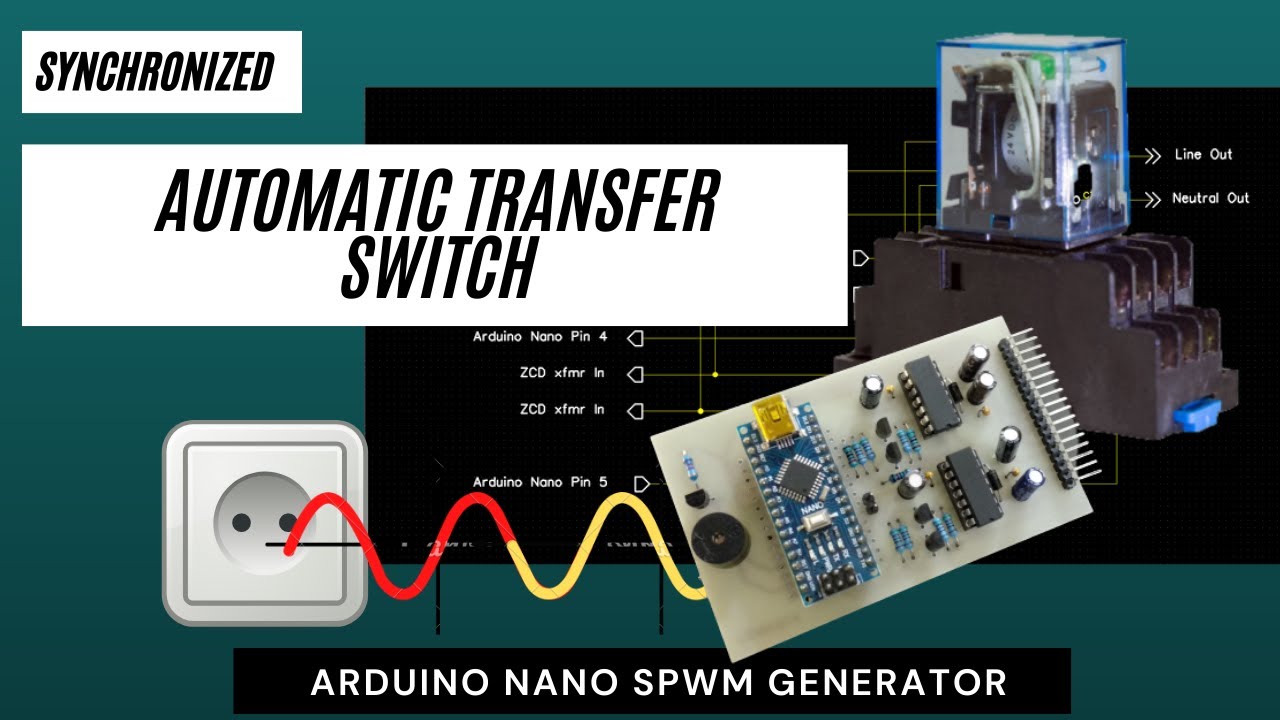
This post is about an Arduino nano SPWM generator with added automatic transfer switch function.
Used to switch the operation of the Inverter to the Grid when the battery voltage drops to a certain level. And it is done synchronously, i.e. the transfer is done when the grid and inverter have the same phase
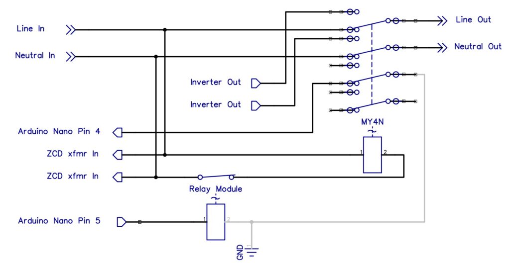
Transfer Switch Circuit
Here I added some circuits and code to the projects that I posted before. The Zero Crossing Detector circuit can be seen in the Grid Synchronization post, while for the SPWM generator please look at the Arduino Nano SPWM Generator post.
the circuit that I added is a 220Vac relay and a 5V module relay that functions as a transfer switch. The picture below is a circuit for the added relay.
Meanwhile, I replaced the 16×2 LCD with a 20×4 LCD because more information will be displayed. Parameters that will be displayed in addition to voltage, battery, and temperature are also displayed frequency of Lock/Unlock status and Grid/Inverter status.
Code
Initialization
Starting with changing the dimensions of the LCD from 16×2 to 20×4 characters so that it is necessary to change the definition of the LCD.
LiquidCrystal_I2C lcd(0x27, 20, 4);Because there is an addition of a relay, the initialization of the relay is added to the setup.
pinMode(4, INPUT_PULLUP);
pinMode(5, OUTPUT);
Zero Crossing Detector ISR
Furthermore, regarding the interrupt service routine for the zero crossing detector, there is a change in the way of writing compared to the previous post and there are additions as well.
void phaseDet()
{
int lockTest;

if (numXtd<200) ICR1--;           // increasing freq.
if (numXtd>200) ICR1++;           // decreasing freq.
if (num<99 && phs==0) num++;      // moving forward phase angle
if (num>0 && phs==1) num--;       // moving backward phase angle
ICR1=constrain(ICR1,780,820);
lockTest=constrain(numXtd,199,201);
if (lockTest==numXtd) lockDet++; else lockDet=0;      // lock detection 0 = unlock
if (lockDet>100) lockDet=100;
numXtd=0;
}
I will not discuss how to increase or decrease the frequency and advance or reverse the phase angle here. I’ll only cover adding code here.
I limit the ICR1 value between 780 to 820 to limit the output frequency which can only change between 49Hz to 51Hz.
Then the lockTest variable here is used to test the condition of the inverter phase angle to the grid. If the difference between the two is only +/- 1.8 degrees then I consider it locked. The locked state can occur only for a moment and then unlock again, to ensure that the locked state occurs continuously, this state is recorded in the lockDet variable.
I do this so that when a switch is moved, the generated signal is quite stable. Here it takes at least 100 locks detected continuously (2 seconds for a 50Hz system), when for example at the 90th detection an unlock occurs, then lockDet will reset to zero and wait for the next 100 continuous locks.
Feedback Processing
The shifting operation occurs when the battery charge drops to a certain level and the phase angle is in phase. Thus the program for this is associated with checking the battery voltage. There is additional coding to the feedback test to read the battery condition and take appropriate action.
  if (battIn <= 475 && lockDet==100 && numXtd<201) status=1;
  if (battIn >= 550 && lockDet==100 && numXtd<201) status=2;
  stndBy(status);
The first is switching from inverter to grid when the battery voltage drops to 11V. In this case, the status variable is assigned a value of one.
The second is switching from grid to inverter when the battery voltage returns to full charge voltage. In this case, the status variable is assigned a value of two.
Both are executed by calling a new function named stndBy.
void stndBy(int status){
    if (status==1) {DDRB = 0; digitalWrite(5,HIGH); }
    if (status==2) {DDRB = 0b00011110; digitalWrite(5,LOW);}
    if (status==0 && digitalRead(4)==LOW){
      while (lockDet!=100){}
      digitalWrite(5,LOW);
    }
}
In the first condition i.e status==1, the SPWM output is turned off and deactivates the relay connected to Arduino pin 5. Thus the relay will connect the load to the grid and the inverter is off.
In the second condition i.e status==2, the SPWM output is turned on and activates the relay to connect the load back to the inverter.
Regarding status==0, this is a condition where the grid is installed but the inverter has not been turned on, when the inverter is turned on, the load will be transferred to the inverter when the phase angle is the same.
That’s the function of ATS that I tried in this project. Also, there are some additions to the LCD display, but I won’t go into them because they are basically the same way as the previous project.
That’s all about my project for this time, hope it’s useful… Have a nice day…
Congratulations Sir,
I would like You to send me they ATS file.
I fallow You since a time.
Thanks , your proyectos are very intersting and very importante for me, I’m working in that one for a time.
Thanks for your time.
Thank you very much for your kind words and for following my work! I’m really glad that the projects are useful and interesting for you.
All the files, are already included in the download package on the release page.
Just grab the zip file and you’ll have the complete ATS project ready to open.
If you have any trouble opening the files or need help with anything specific, feel free to let me know. Happy building, and good luck with your project! 🚀
Thank you for your video. I would like to try your circuit however, it does not include the library.
Thanks! Actually, no external library is needed as it uses the standard ones already included in the Arduino IDE.