▶️ Watch on YouTube …
In this project, I am trying to make a Sinusoidal Pulse Width Modulation using the ESP32 microcontroller and MCPWM. The objective of this experiment is to get a SPWM signal without using a Look Up Table, which allows for generating a variable frequency SPWM signal.
Due to many questions about how to generate SPWM, in this post, I will discuss it from the basics.
Introduction
Here, I will explain the foundation of the project to build an SPWM generator using ESP32.
Definition of SPWM
(Sinusoidal Pulse Width Modulation) is a modulation technique used to modulate the amplitude of a sinusoidal wave by changing the pulse width of a high-frequency wave.
In SPWM, the amplitude of the modulating signal determines the pulse width of the generated SPWM wave. Therefore, SPWM generates a sinusoidal wave with accurately and consistently controlled amplitude.
Importance of SPWM in power electronics
SPWM is very useful in electrical and electronic applications, such as inverter power control, motor control, and energy conversion systems.
The main advantage of SPWM is better results in terms of efficiency, power factor, and signal quality compared to other modulation techniques, such as amplitude modulation.
Overview of the ESP32 microcontroller
ESP32 is a low-cost and energy-efficient microcontroller with dual-core processing, Wi-Fi and Bluetooth connectivity, and various interfaces and I/O peripherals. Designed for use in Internet of Things (IoT) applications, such as smart home automation, wearables, wireless communications and networks, and motor control (ESP32 MCPWM).
With its high processing power, low power consumption, and cost-effectiveness, ESP32 has become a popular choice among makers, hobbyists, and developers for various projects.
Additionally, its development environment, including available tools and software, makes it easy to program and implement in various applications.
Purpose of the project
The main objective of this project is to create a Pulse Width Modulation (SPWM) signal using direct sinusoidal calculations, without using a Look-Up table. We expect to achieve more accurate and efficient results in changing modulation frequency by using this method. In this project, we will use the ESP32 microcontroller as a platform to process and create the SPWM signal through the MCPWM peripheral.
The process of creating the SPWM signal will involve several steps, starting from programming the ESP32 microcontroller, testing and validating direct sinusoidal calculations, and monitoring and controlling the generated SPWM signal. The final goal of this project is to obtain an SPWM signal that meets the desired specifications and has good quality.
By completing this project, it is expected to gain new knowledge and skills in the field of microcontrollers and modulation techniques, as well as enriching understanding and application of SPWM technology in various fields. Additionally, this project will also help in simplifying the process of changing modulation frequency, because it uses direct sinusoidal calculations without having to use a Look-Up table.
Theoretical Background
SPWM Basics and Principles
Pulse Width Modulation (SPWM) is a modulation technique that modulates the pulse width of a signal to control the power transmitted to the load. The basic principle of SPWM is to convert a DC signal into an AC signal by modulating the pulse width of the generated AC signal.
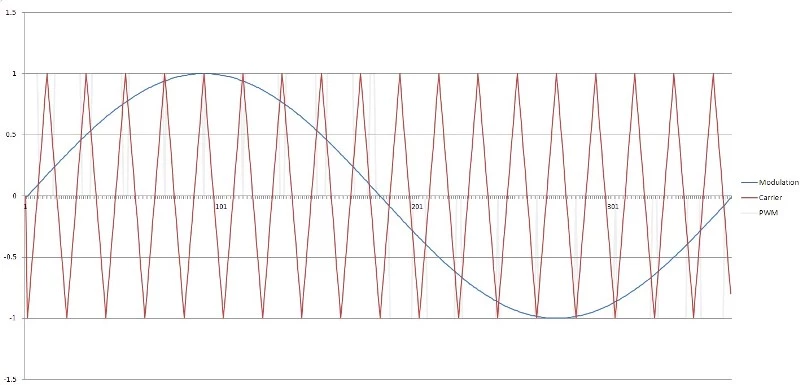
In the application of SPWM, a sinusoidal AC signal is used as a reference and the triangle signal to be controlled is transmitted as an input signal. The modulation process is carried out by comparing the two signals, the reference signal and the input signal. The result of this comparison is a signal with a pulse width that changes with the magnitude of the input signal.
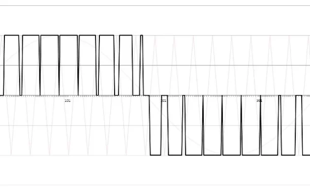
The width of the SPWM signal pulse will affect the amount of power transmitted to the load. The greater the width of the SPWM signal pulse, the greater the power transmitted to the load will be. Conversely, the smaller the width of the SPWM signal pulse, the smaller the power transmitted to the load will be.
Thus, SPWM has several advantages, such as having a fast response and ease of changing the amount of power transmitted to the load, as well as having a low level of distortion. In its applications, SPWM is often used in various applications, such as motor control systems, power load control systems, and AC signal control systems.
Mathematical Modeling of SPWM
In the mathematical modeling process, a sinusoidal reference AC signal is used as a basis for modulating the pulse width of the DC signal to be controlled.
The mathematical modeling of SPWM can be applied by using the following formula:
V(t) = Vm * sin (2 * π * f * t)
where,
V(t) = reference sinusoidal AC signal
Vm = amplitude of the reference signal
f = frequency of the reference signal
t = period of carrier signal
Circuit Design
Overview of the hardware components
In this project, I used the same circuit as the SPWM generator project, only I replaced the Arduino Nano with an ESP32. Similarly, for the full-bridge MOSFET, I used the same as in the EGS002 inverter project with the IRF3205 MOSFET.
The coding must solve some problems related to the hardware. Here I will briefly discuss it because the focus of this project is on the SPWM (software) generation using the MCPWM peripheral on the ESP32.
The flywheel effect on the inductor causes these problems, although the body diode solves it by acting as a freewheeling diode, but it does not fully solve this effect. To solve this, we will use complementary mode PWM in the coding, which means that the top and bottom MOSFETs will always work in opposition.
Another issue is that in this complementary mode, cross conduction can occur on the MOSFET due to tON and tOFF not being equal, to solve this by functioning Deadtime.
The discussion about these is a separate discussion about the Full-Bridge MOSFET hardware.
Circuit schematic diagram
The SPWM generator and full-bridge MOSFET schematic is as follows:
In this project, I use the TLP250 driver for Arduino Nano and connect it to ESP32 using jumper wires.
And for Full Bridge MOSFET driver I use the circuit below:
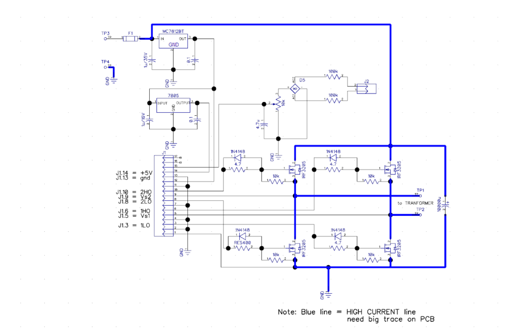
This is the same circuit as the circuit in my post about Simple Inverter.
ESP32 MCPWM Code Implementation
Overview of the ESP32 MCPWM
When creating software related to the hardware in the SPWM generation process, developers need to consider several factors, such as project specifications, and the appropriate use of I/O ports, timers, interrupts, and operators in the MCPWM module.
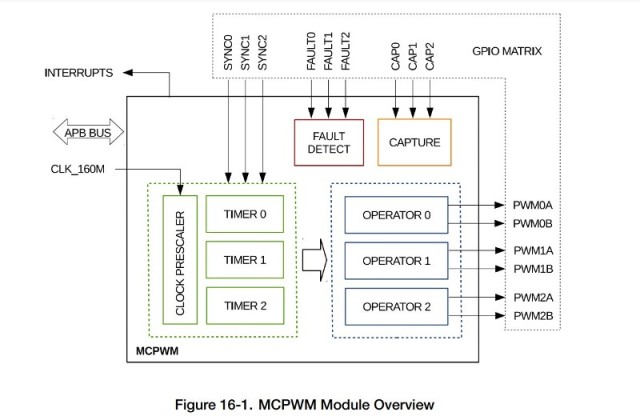
The above diagram is the MCPWM (Motor Control Pulse Width Modulation) block, which is one of the peripherals of the ESP32. There are two MCPWM, MCPWM0 and MCPWM1, that can be used and each MCPWM has one prescaler, three timers, operators and PWM ports. In addition, there is a Fault Detect and Capture submodule for motor control purposes.
Prescaler
Timers are used in SPWM generation to manage time and ensure that each SPWM cycle is executed at a specific time. The clock signal used is CLK_160M (160 MHz or 6.25 ns) which is first reduced by the Prescaler.
The Prescaler can be set through the configuration register in the MCPWM by filling in PWM_CLK_PRESCALE between 0 and 255. Period of PWM_clk = 6.25ns * (PWM_CLK_PRESCALE + 1). Initializing the prescaler and timer will determine the period time of the PWM clock, for example, for PWM_CLK_PRESCALE = 15, a PWM_clk 100 ns will be obtained.
Timer
To determine the frequency or period of the carrier signal, we need to make adjustments to the timer. This setting also affects the event signal for the interrupt.
In addition, developers must determine the operating mode of the timer, such as up counter mode, down counter mode, and up-down counter mode, in advance in the timer submodule.
For the SPWM generation, I use the up-down counter mode with consideration that this mode produces symmetrical pulses.
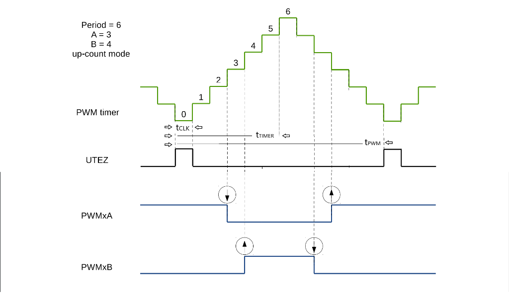
• Count-Up-Down Mode: This is a combination of the two modes mentioned above. The PWM timer starts increasing from zero until the period value is reached. Then, the timer decreases back to zero. This pattern is then repeated. The PWM period is the result of (the value of period register × 2 + 1). esp32_technical_reference_manual_en.pdf p.412
The counter will up to a certain value entered in the register and then down to zero. The example in the above figure is for the counter value 6, the counter will rise to 6 and then fall. The rise period and fall period are each counted as one timer period, so the up-down period is counted as two timer periods. Therefore, the frequency x 2 or the period / 2.
Operator
The operator submodule is responsible for generating a pair of PWM signals based on the timing reference determined by the PWM timer and its duty mode. In addition, the operator submodule also inserts Deadtime for each pair of PWM generated.
For example, the above figure shows the PWMxA and PWMxB outputs for the complementary duty_mode, that is, PWMxA active high and PWMxB active low.
At cmpr_a = 3 and cmpr_b = 4, PWMxA will change logic to low when the counter reaches the value 3 and PWMxB at counter = 4 will change to high. The cmpr_a and cmpr_b values will determine the pulse width.
Interrupt
Interrupt allows the microcontroller to handle pulse width modulation setting tasks, without being affected by the main operations of the microcontroller.
Because we need to update the pulse width value at certain times, the interrupt becomes the main thing. This is where the sine value calculation and pulse width value update take place to ensure high accuracy for each SPWM cycle and a stable and accurate output signal.
MCPWM can trigger several events, one of which is the TEZ event indicating that the timer has reached zero. This event will be used to trigger the interrupt.
Programming the ESP32 microcontroller using the Arduino IDE
To use ESP32 with the Arduino IDE, first you need to add the ESP32 board to the Arduino IDE. The way to do this is as follows:
- Open Arduino IDE
- Click File -> Preferences
- In the “Additional Board Manager URLs” column, add the link “https://dl.espressif.com/dl/package_esp32_index.json”
- Click Tools -> Board: -> Board Manager
- Search and select “esp32” and click “Install” After completion, restart the Arduino IDE.
- Click Tools -> Board -> ESP32 Dev Module
Or for more information please see the link: https://espressif-docs.readthedocs-hosted.com/projects/arduino-esp32/en/latest/installing.html
After that you can start writing and uploading code to ESP32 using the Arduino IDE.
The ESP32 board used in this experiment is the ESP32 Devkit V1.
ESP32 MCPWM SPWM generation code using the timer interrupt function
Library Inclusion
In order to use the MCPWM function, include the library first, which is mcpwm.h
#include <driver/mcpwm.h> This library includes functions for initializing MCPWM, setting duty cycle, frequency, I/O, and other relevant parameters.
Variable Declaration
Declare the required variables and the pins used in the program to be created. Give names to the ESP32 pins and variables that are easy to remember.
const int LO1 = 12;                        // Pin used for PWM output
const int HO1 = 13;                        // Pin used for PWM output
const int LO2 = 14;                        // Pin used for PWM output
const int HO2 = 27;                        // Pin used for PWM output

const float freqCarr = 20000.0;            // Carrier freq.
float freqMod = 50.0;                      // Modulation Frequency Hz
int amplitude = 300;                       // max counter/timer value
int sampleNum = int(freqCarr/freqMod);     //
int i;
Setup
Initialize all that is needed for SPWM generation on the ESP32 in the void setup().
Pins 12 and 13, which are the SPWM signal outputs, I initialize using the mcpwm library to work on the MCPWM0 module with OPERATOR0 where output PWM0A uses pin 12 (LO1) and PWM0B on pin 13 (HO1).
Meanwhile, pins 14 (LO2) and 27 (HO2) are initialized as outputs like in a regular Arduino. Pin 23 is prepared as an output for debugging or other purposes.
  mcpwm_gpio_init(MCPWM_UNIT_0, MCPWM0A, LO1);  // Use GPIO 12 for MCPWM0A
  mcpwm_gpio_init(MCPWM_UNIT_0, MCPWM0B, HO1);  // Use GPIO 13 for MCPWM0B
  pinMode(LO2, OUTPUT);
  pinMode(HO2, OUTPUT);
  pinMode(23, OUTPUT);                          // for test purposes
Next, after setting the I/O port, the next step is to set the parameters for PWM generation which include the frequency, duty cycle, counter operation mode, PWM output mode and the timer used. In this case, the initialization also uses the mcpwm library.
mcpwm_config_t pwm_config;
  pwm_config.frequency = freqCarr * 2 ;              // Set frequency in Hz
  pwm_config.counter_mode = MCPWM_UP_DOWN_COUNTER;   // phase freq correct
  pwm_config.duty_mode = MCPWM_DUTY_MODE_0;          // active high PWM
  pwm_config.cmpr_a = 0;                             // duty cycle to 0%
  pwm_config.cmpr_b = 0;                             // duty cycle to 0%
mcpwm_init(MCPWM_UNIT_0, MCPWM_TIMER_0, &pwm_config); // init PWM
By calling mcpwm_init, those values are initialized in MCPWM0 and TIMER0
Next, install an interrupt for the MCPWM, which is MCPWM_ISR on MCPWM0, so that MCPWM_ISR will be called when the desired event occurs.
mcpwm_isr_register(MCPWM_UNIT_0, MCPWM_ISR, NULL, ESP_INTR_FLAG_IRAM, NULL);The function above is used to register the interrupt and the corresponding interrupt service routine that is triggered when a specific event occurs. After that, the function chooses and activates an event that will trigger the execution of the ISR.
Unfortunately, the function for enabling the interrupt is not available (I couldn’t find it) in the mcpwm.h library. Due to the importance of the interrupt, I enable it directly by initializing the hardware register, although this method is not recommended (HARD CODE!!!).
WRITE_PERI_REG(0x3FF5E110, BIT(3));In the INT_ENA_PWM_REG register, there are 30 bits that can be selected to enable an interrupt (see page 480 of the esp32_technical_reference_manual_en.pdf).
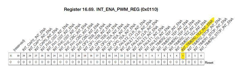
BIT(3) is the interrupt enable for the TEZ event and this is what I activate because I need it when the timer returns to zero, the interrupt event occurs and the program execution will switch to MCPWM_ISR.
Interrupt
In SPWM generation, the interrupt routine plays a key role because it is in this routine that the pulse width value is updated with a new value. Additionally, in this project, I tried to calculate the sine value in this routine and not use a Look Up Table.
By directly calculating the sine value in real-time in the interrupt routine, this will make it possible to generate SPWM with a variable frequency. The formula: V(t) = Vm * sin (2 * π * f * t) as previously mentioned is adapted to the coding as:
sineValue= amplitude * sin (2 * PI * freqMod * (i /freqCarr));The variable “sineValue” contains the pulse width value for time “i“, where “i” ranges from zero to the number of pulses in one cycle of the modulation sine. The value of the “sineValue” variable has positive (>0) and negative (<0) values, so I use it as an indicator of the positive and negative cycles.
  if (sineVal>0)  {
    mcpwm_set_duty(MCPWM_UNIT_0, MCPWM_TIMER_0, MCPWM_GEN_A, sineValue);
    digitalWrite(LO2,1);
  }
The ISR ends by changing the value of i for the calculation of pulse width in the next event.
i++;
if (i > sampleNum ) i=0;
I increment the value of i by one for the next calculation or set it to zero if the current value is at the maximum number of pulses per modulation cycle.
Loop
Currently, the focus of work is on generating SPWM, where the main involved coding is in the setup and ISR, so there are no commands in the Loop yet.
Testing and debugging the code
In this section, I will discuss testing and debugging in case any discrepancies are found while generating SPWM using the ESP32 MCPWM peripheral.
ISR Callback
Before, I discussed that the mcpwm.h library did not have a way to enable interrupts, so I had to hard code it. The first thing I did was to test whether the Interrupt was working by looking at the pulse period on the test port (pin 23) using a short program like below.
void IRAM_ATTR MCPWM_ISR(void*) {
  digitalWrite(23,HIHGH);
  digitalWrite(23,LOW);
}
The detection of pulsing at the test port indicates that the ISR has been executed, but the period does not match the expected carrier frequency. With freqCarr = 20,000, the expected period is 50 uS (20 kHz), but the measurement result provides a significantly different value.
Trying to change freqCarr to different values does not result in any changes in the output, thus this discrepancy is not due to the timer initialization.
Referring back to the datasheet, there is an INT_CLR_PWM_REG register in the ESP32 MCPWM. I suspect that the ESP32 system does not automatically reset the interrupt that occurs, causing the system to execute the ISR repeatedly after it has been executed once.
To confirm this, I tried to turn off the interrupt flag through the program, but unfortunately I could not find a function for it, so I had to resort to hard coding the register again.
void IRAM_ATTR MCPWM_ISR(void*) {
  WRITE_PERI_REG(0x3FF5E11C, BIT(3));    // HARD CODE!!! clear TEZ interrupt
  digitalWrite(23,HIHGH);
  digitalWrite(23,LOW);
}
By clearing the TEZ flag, the frequency indication has now changed, although not exactly as expected (20 kHz), but changing the freqCarr value in the setup now works.
Timer Periode
Initializing the frequency or period through mcpwm_init resulted in a slightly higher frequency (20.83 kHz). I tried to correct it by directly entering the desired value into the register. The value I expected was 20 kHz or 50 uS, while the clock on the ESP32 is 6.25 nS (160 MHz), so I need to calculate the number of clocks required to reach 50 uS.
WRITE_PERI_REG(0x3FF5E000, 0);                  // PWM_CLK_CFG_REG pwm_clock = 6.25 nS
tmrRegVal = (((1/freqCarr)/2)/6.25E-9)-1;       // PWM_TIMER0_CFG0_REG period update immediately no prescaler
WRITE_PERI_REG(0x3FF5E004, int(tmrRegVal)<<8);  // timer period = (pwm period /2) / 6.25nS
WRITE_PERI_REG(0x3FF5E03C, 0);                  // PWM_GEN0_STMP_CFG_REG time stamp update immediately
This resetting results in a frequency of 2 kHz which should have been 20 kHz with a pwm_clock of 6.25 nS, meaning the pwm_clock is 62.5 nS. For now, I’ll ignore this issue and change the value of the divider (pwm_clock) for period calculation to 62.5 ns.
tmrRegVal = (((1/freqCarr)/2)/62.5E-9)-1;And the result was as expected, which was 20 kHz, similarly if I change the freqCarr value to a different frequency the measurement results match the input value.
ISR SPWM generator
As explained earlier, the mcpwm_set_duty function is used to enter the result of the sine calculation and change the width of the PWM pulse accordingly. However, using this function still results in something that confuses me once again, for now, I’ll ignore this and I’ll use a hard-coded approach.
WRITE_PERI_REG(0x3FF5E040, sineVal);The ISR callback discussed in point 1 above is now using as the ISR callback for generating SPWM as follows.
void IRAM_ATTR MCPWM_ISR(void*) {
  float sineValue;
  int sineVal;

  WRITE_PERI_REG(0x3FF5E11C, BIT(3));    // HARD CODE!!! clear TEZ interrupt

  sineValue=  amplitude * sin (2 * PI * freqMod * (i /freqCarr));
  sineVal = int (sineValue+0.5);
  if (sineVal>0)  {
    WRITE_PERI_REG(0x3FF5E040, sineVal);              //PWM_GEN0_TSTMP_A_REG
    digitalWrite(LO2,1);
  }
  if (sineVal<0) {
    WRITE_PERI_REG(0x3FF5E040, 400 + sineVal);       //PWM_GEN0_TSTMP_A_REG
    digitalWrite(HO2,1);
  }
  if (i==0 ) {
    digitalWrite(HO2,0);
    WRITE_PERI_REG(0x3FF5E040,0);//  400 + sineVal);      //PWM_GEN0_TSTMP_A_REG
  }
  if (i==(sampleNum/2 )) {
    digitalWrite(LO2,0);
    WRITE_PERI_REG(0x3FF5E040,400);//  400 + sineVal);      //PWM_GEN0_TSTMP_A_REG
  }
  i++;
  if (i > sampleNum ) i=0;            // clear i when > 1 cycle (360 deg)
}
The steps taken in this ISR are:
- Clear the Interrupt Flag
- Calculate the Sinusoidal value for the nth period and convert it to an integer
- Enter the value in the register for the pulse width according to its cycle: positive cycle (>0), negative cycle (<0) or at zero cross (i = 0 and i > sampleNum/2).
- Increment i for use in the next interrupt.
- Return
The value calculated at this time is saved in the shadow register on the timer and will be used when the event occurs.
Results
ESP32 SPWM output waveforms
The image below is the output of a 50 Hz fundamental signal (yellow) and an SPWM signal with a 20 kHz carrier frequency (blue).
And the following image is the same signal on a smaller time base.
The image clearly shows a change in pulse width on the SPWM output from small to large.
Here is an image for the SPWM signal of PWM0A (LO1) and PWM0B (HO1) ports for Deadtime measurement.
The measured Deadtime is 200 ns, in accordance with the initialization of Deadtime of (31+1) * 6.25 ns.
Inverter output waveforms
Here is a 50 Hz AC signal which is the output of an inverter from 12V DC to 220V AC.
I haven’t paid attention to the amplitude of the 50 Hz AC output because in this project, I only focus on its generation.
Harmonic of the SPWM waveform
The harmonics produced are as shown in the following image.
The image shows that the 3rd and 5th harmonics are quite large. If measurements are taken in Vrms, the data obtained is as follows:
Fundamental (f1): 10.2 Vrms, Harmonic3 (f3): 400 mVrms, Harmonic5 (f5): 200 mVrms
Therefore, the calculated THD result is 5.8%.
ISR execution time
I conducted a measurement of the execution time for this mcpwm ISR to get an idea of how fast the ESP32 performs mathematical calculations. This is important because mathematical calculations generally require the floating-point unit, which consumes a lot of microcontroller resources.
From the measurement, I obtained a maximum time of 16.8 microseconds, which still leaves plenty of time to perform other processes within one PWM period.
Conclusion
Summary of the project results
Generating SPWM using the MCPWM peripheral on the ESP32 can be done without using a Look Up Table due to its fast processing speed.
The ESP32 has a high clock frequency of 160 MHz, and its 32-bit processor is very useful for processing calculations, in this case, sine wave calculations.
Thus, the development of SPWM using the MCPWM peripheral of the ESP32 provides hope for projects such as SPWM for 3 phases variable speed as well as other project.
Code ESP32 SPWM using MCPWM
/*
ESP32 SPWM_5.ino

Created : 14/02/2023
Author  : yopie DIY


SPWM generation using ESP32 MCPWM peripheral

Left bridge used for fundamental signal (50Hz), Right bridge for SPWM (20kHz carrier freq.)
Using real time sine calculation instead of Look-Up Table

Copyright (C) 2023 yopie DIY

This program is free software: you can redistribute it and/or modify
it under the terms of the GNU General Public License as published by
the Free Software Foundation, either version 3 of the License, or
(at your option) any later version.

This program is distributed in the hope that it will be useful,
but WITHOUT ANY WARRANTY; without even the implied warranty of
MERCHANTABILITY or FITNESS FOR A PARTICULAR PURPOSE.  See the
GNU General Public License for more details.

You should have received a copy of the GNU General Public License
along with this program.  If not, see <https://www.gnu.org/licenses/>.
*/

/*------------------------------------------------------------------------*/

#include <driver/mcpwm.h>

const int LO1 = 12;                        // PWM output pin Low Side
const int HO1 = 13;                        // PWM output pin High Side
const int LO2 = 14;                        // output pin Low Side
const int HO2 = 27;                        //  output pin High Side
const float freqCarr = 20000.0;            // Carrier freq. Hz
float freqMod = 50.0;                      // Modulation freq. Hz
int amplitude = 300;                       // Amplitude of Sine Wave Output
int sampleNum = int(freqCarr/freqMod);     // samples per cycle sine wave
int i;                                     // PWM index number


/*-------------------------- Define the ISR function ---------------------*/
void IRAM_ATTR MCPWM_ISR(void*) {
  float sineValue;
  int sineVal;

  WRITE_PERI_REG(0x3FF5E11C, BIT(3));            // INT_CLR_PWM_REG
                                                 // clear interrupt
// digitalWrite(23, HIGH);
  sineValue=  amplitude * sin (2 * PI * freqMod * (i / freqCarr));
  sineVal = int (sineValue + 0.5);               // integer rounding
  if (sineVal>0)  {                              // Pos half of sine wave
    WRITE_PERI_REG(0x3FF5E040, sineVal);         // PWM_GEN0_TSTMP_A_REG
    digitalWrite(LO2,1);                         // sine value->register
  }
  if (sineVal<0) {                               // Neg half of sine wave
    WRITE_PERI_REG(0x3FF5E040, 400 + sineVal);
    digitalWrite(HO2,1);
  }
  if (i==0 ) {                                   // Zero cross (0 deg)
    WRITE_PERI_REG(0x3FF5E040,0);
    digitalWrite(HO2,0);
  }
  if (i==(sampleNum/2 )) {                      // Zero Cross (180 deg)
    WRITE_PERI_REG(0x3FF5E040,400);
    digitalWrite(LO2,0);
  }
  i++;
  if (i > sampleNum ) i=0;                      // reset i if > 1 cycle
//  digitalWrite(23, LOW);
}

/*------------------------------------------------------------------------*/
void setup() {

  pinMode(23, OUTPUT);
  pinMode(LO2, OUTPUT);
  pinMode(HO2, OUTPUT);
  mcpwm_gpio_init(MCPWM_UNIT_0, MCPWM0A, LO1);   // Use GPIO 12 for MCPWM0A
  mcpwm_gpio_init(MCPWM_UNIT_0, MCPWM0B, HO1);   // Use GPIO 13 for MCPWM0B

  mcpwm_config_t pwm_config;
  pwm_config.frequency = freqCarr * 2 ;           // up-down ctr->freq*2
  pwm_config.cmpr_a = 0;                          // duty cycle to 0%
  pwm_config.cmpr_b = 0;                          // duty cycle to 0%
  pwm_config.counter_mode = MCPWM_UP_DOWN_COUNTER;// phase freq correct
  pwm_config.duty_mode = MCPWM_DUTY_MODE_0;       // active high PWM
  mcpwm_init(MCPWM_UNIT_0, MCPWM_TIMER_0, &pwm_config);

  WRITE_PERI_REG(0x3FF5E000, 0);                  // PWM_CLK_CFG_REG
                                                  // pwm_clock no prescaler
  float tmrRegVal = (((1/freqCarr)/2)/62.5E-9)-1; // timer period calc
  WRITE_PERI_REG(0x3FF5E004, int(tmrRegVal)<<8);  // PWM_TIMER0_CFG0_REG
  WRITE_PERI_REG(0x3FF5E03C, 0);                  // PWM_GEN0_STMP_CFG_REG
                                                  // time update immediately

  // Attach ISR function to MCPWM interrupt
  mcpwm_isr_register(MCPWM_UNIT_0, MCPWM_ISR, NULL, ESP_INTR_FLAG_IRAM, NULL);
  // Deadtime i.e (31 + 1) * 6.25 nS
  mcpwm_deadtime_enable(MCPWM_UNIT_0, MCPWM_TIMER_0, MCPWM_ACTIVE_HIGH_COMPLIMENT_MODE , 31, 31);
  // INT_ENA_PWM_REG enable interrupt on TEZ
  WRITE_PERI_REG(0x3FF5E110, BIT(3));
//  Serial.begin(115200);
}

/*-----------------------------------------------------------------------*/
void loop() {
  // nothing to do right now.....
}
Pingback: 3-Phase Inverter using ESP32 SPWM Generator • Yopie DIY