▶️ Watch on YouTube …
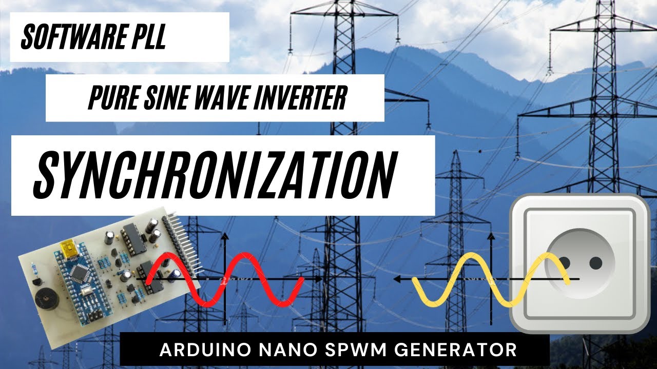
This post is still continuing my project in Arduino Nano SPWM generator. I add some code and also Zero Crossing Detector circuitry for Grid Synchronization. The circuit is to detect the grid phase and the code is doing a task as Software Phase Loop Lock. Using Software Phase Locked Loop (SPLL) it’s a lot easier than using the hardware PLL approach when processing this function.
Software Phase Locked Loop.
Here I try to apply the software phase lock loop in the process of equalizing the phase angle. In addition to equalizing the phase angle, this method will also equalize the frequency.
Below is the Block diagram for the PLL (hardware).
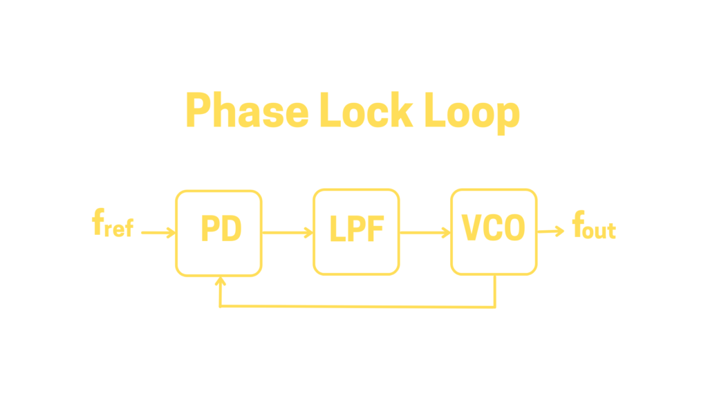
The building blocks of PLL are Phase Detector (PD), Low Pass Filter (LPF), and Voltage Control Oscillator (VCO). While in SPLL the blocks are PD, Proportional Integral (PI) controller and Numerical Control Oscillator (NCO).
The PD section detects the phase angle difference between the reference (grid) and the NCO. I use ZCD to convert the AC signal into a square signal, the detection itself is done by the software.
The LPF section or called the loop filter functions to determine the dynamics of the loop, and responds to disturbances such as changes in frequency by providing voltage corrections to the VCO. In SPLL this is replaced by a PI controller which processes the disturbance signal into an NCO correction signal in the form of data.
The SPWM generated by Arduino is basically an oscillator but controlled by data instead of voltage, this is called a Numerical Control Oscillator (NCO). Controlling the value of ICR1 means controlling the oscillator output frequency.
Zero Crossing Detector.
The schematic below is the Zero Crossing Detector circuit used in this project. Using one Dual Op-Amp LM358 as Voltage Comparator and Diode Clipper circuit as Zero Cross Detector.
Actually, this circuit can be connected directly to the mains voltage but for safety reasons, I use a transformer to step down the voltage and also make galvanic isolation t the grid.
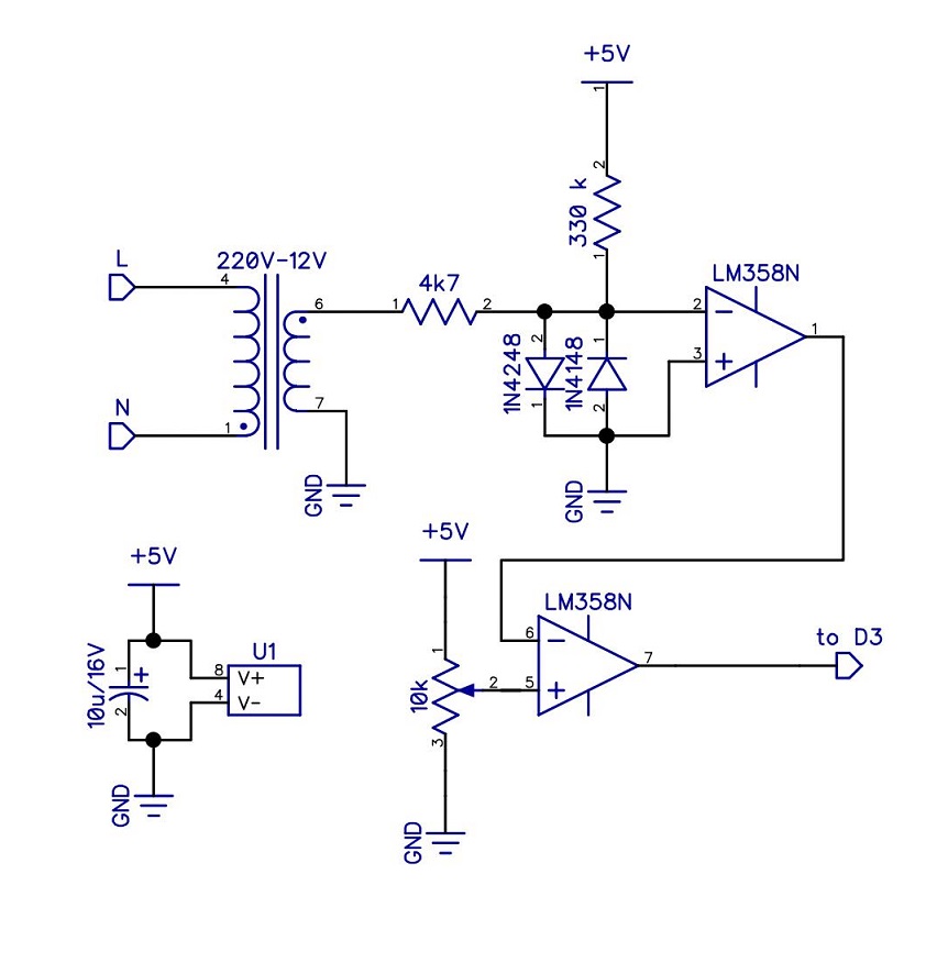
This zero crossing detector circuit produces a High signal when a positive cycle occurs at the input, and a Low when a negative cycle occurs. There is a slight phase angle shift between the input and the output but for now, I’ll ignore it.
The above circuit is connected to the Arduino D3 port and is used as an interrupt input. The synchronization process is completely dependent on the interrupt that will change the value of the ICR1 timer register.
Changing the value of ICR1 means changing the carrier frequency and its fundamental frequency, for this purpose we need a slight difference in frequency between the inverter and the grid.
We expect the same Frequency with the same phase angle, but in reality, this is not the case. The biggest possibility is the difference in phase angle.
Phase Detection and Synchronization
Connecting the Zero Crossing Detector Output to pin D3 (INT1) on Arduino requires initialization of the interrupt along with its interrupt service routine.
attachInterrupt(digitalPinToInterrupt(3), phaseDet, RISING);So when the RISING pulse is on pin D3 the phaseDet routine will run.
void phaseDet()
{
if (num>0 && phs==1){
 num--;
 ICR1=ICR1+1;
}
if (num<99 && phs==0){      // <------ 50Hz
 num=num+1;
 ICR1=ICR1-1;
}
counterX=0;
}
Interrupt service Routine phaseDet serves as a phase detector as well as a simple PI controller.
When an interrupt occurs, the first thing to do is to check the phase angle between the grid (reference) and the inverter. If the inverter output waveform is behind the grid, it is corrected by advancing the phase angle and also by decreasing the frequency. If in front of it, the phase angle is reversed and the frequency is increased.
The value of num determines the phase angle and ICR1 for the frequency. Both will control the SPWM generation function (NCO) which in this case is the ISR(TIMER1_OVF_vect) function.
This simple SPLL provides synchronization results quite quickly even though the response is still underdamped, as seen by the signal that goes back and forth before a lock occurs. This is due to a very simple loop filter (PI controller).
Thus this is the end of this post, I hope this post can be useful for all of us.
Pingback: Automatic Transfer Switch • Yopie DIY